Periodic steady state
to problem overview

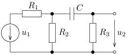
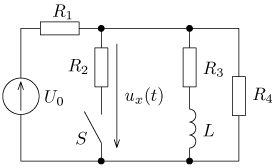
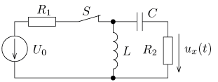
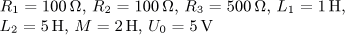
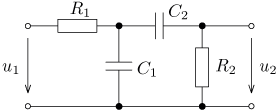
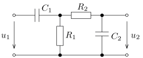
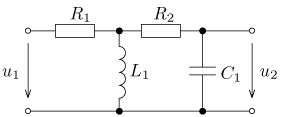
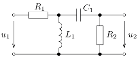
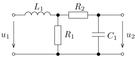
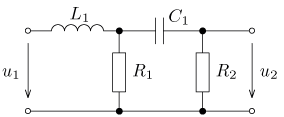
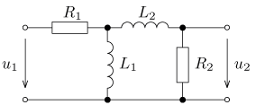
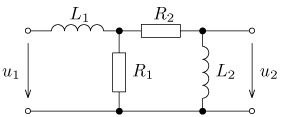
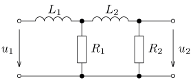
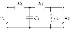
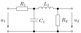
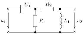
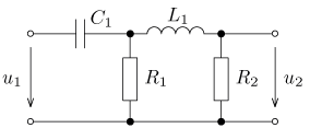
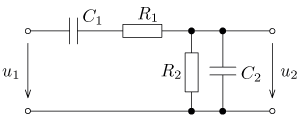
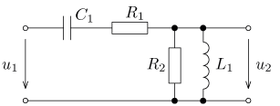
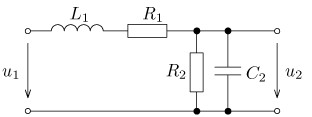
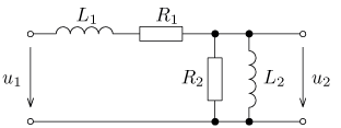
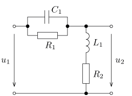
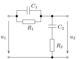
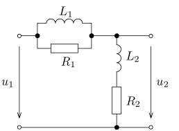
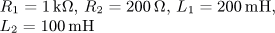
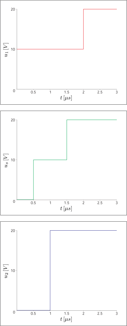
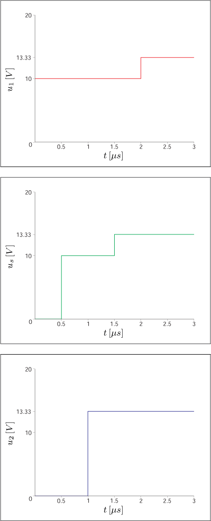
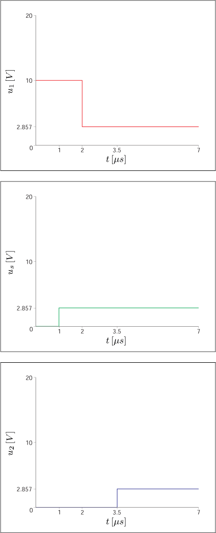
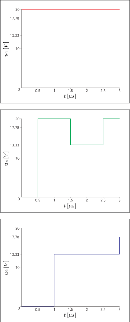
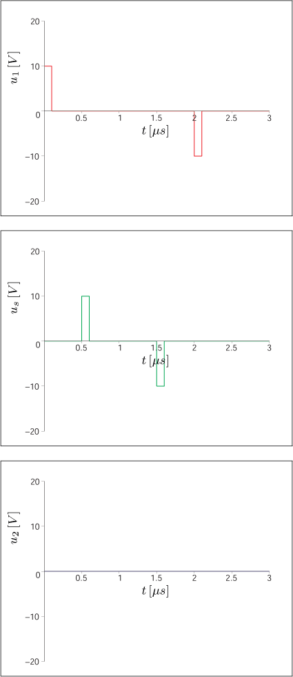
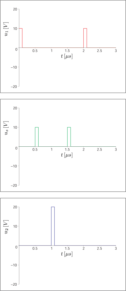
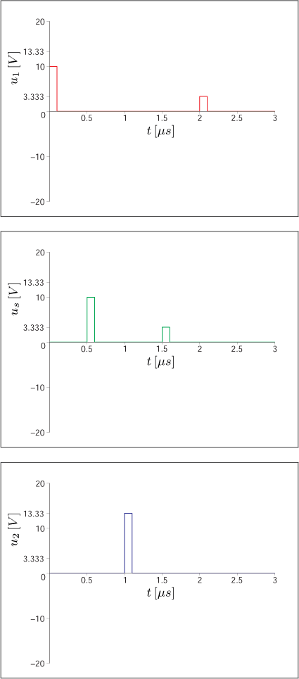
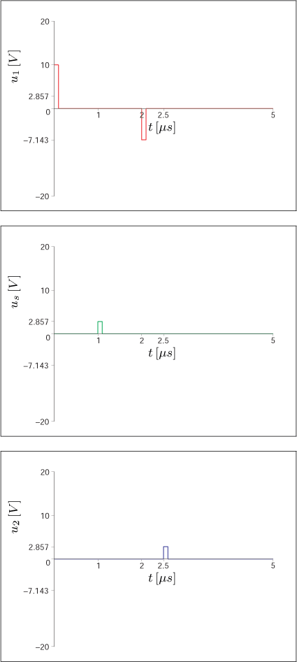
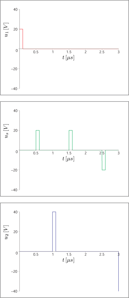
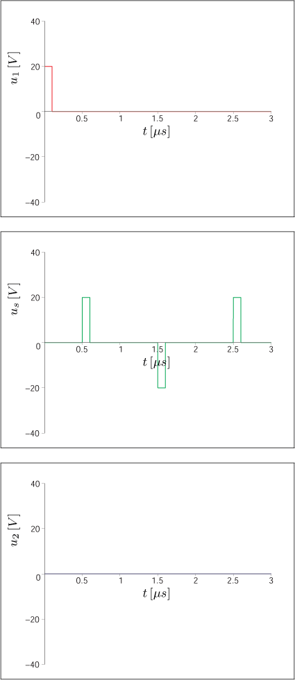
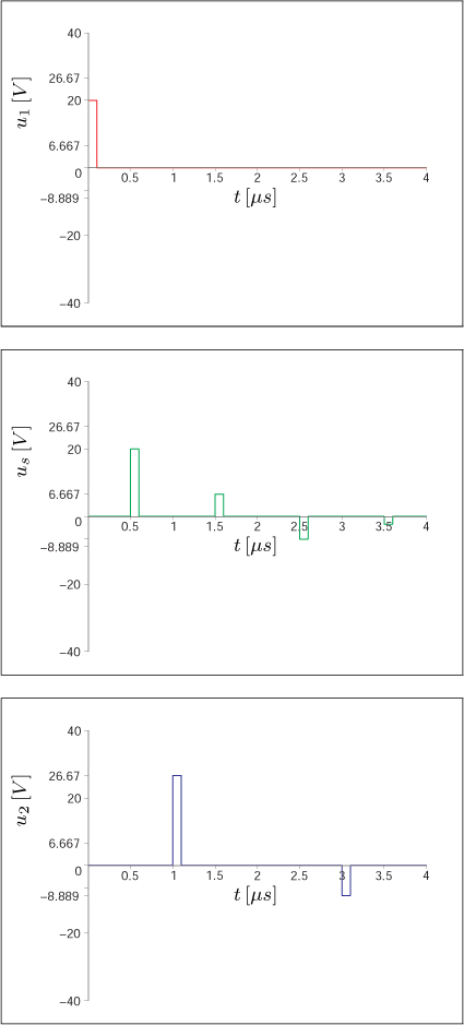
and they are in the steady state. Find the output voltage u 2(t) and
its effective (rms) value U 2.
Back
problem 1
solution
problem 2


solution
problem 3

solution
problem 4

solution
problem 5

solution
problem 6
solution
problem 7

solution
problem 8

solution

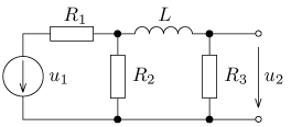
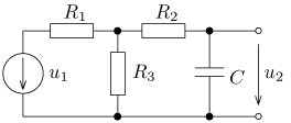
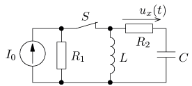
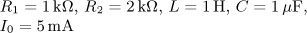
and they are in the steady state. Find the output voltage u2(t) and its effective (rms) value U2.
problem 1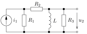  solution | problem 2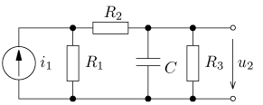  solution |
problem 3  solution | problem 4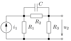  solution |
problem 5 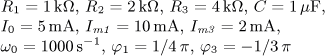 solution | problem 6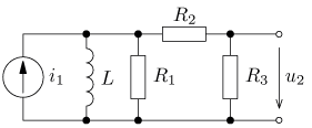  solution |
Use first three non zero harmonics components of the Fourier series (including a DC component, if that is not zero).
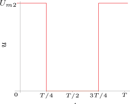
| obr�zek a) | obr�zek b) | Pom�cka: |
|---|---|---|
| 
| 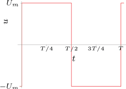 |
| (Standart square wave advanced by amplitude) | (Standart square wave advanced by amplitude and placed symetrically to the voltage axis) | 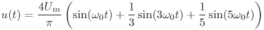 |
problem 1 solution | problem 2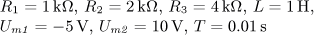 solution |
problem 3 solution | problem 4 solution |
problem 5 solution | problem 6 solution |
problem 7 solution | problem 8 solution |
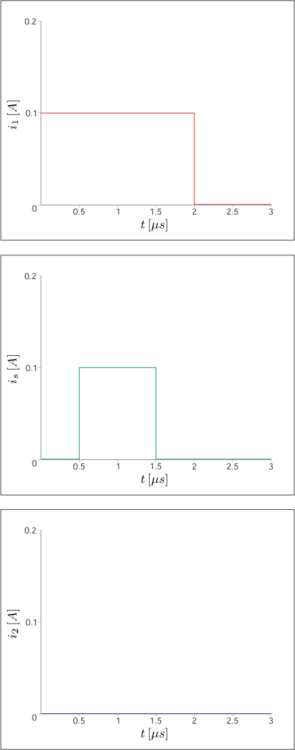
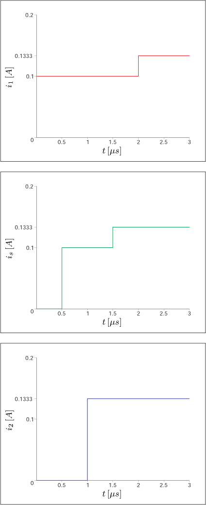
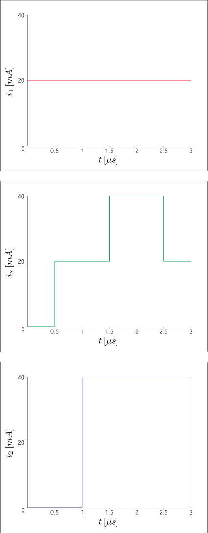
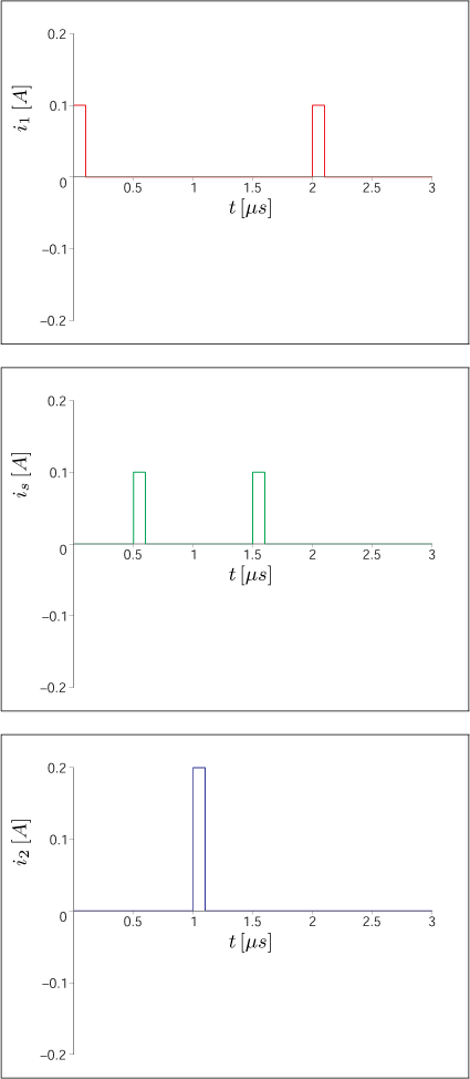
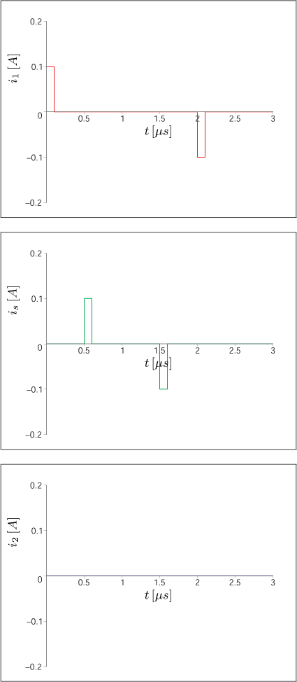
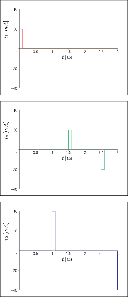
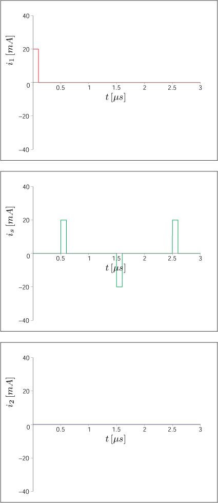
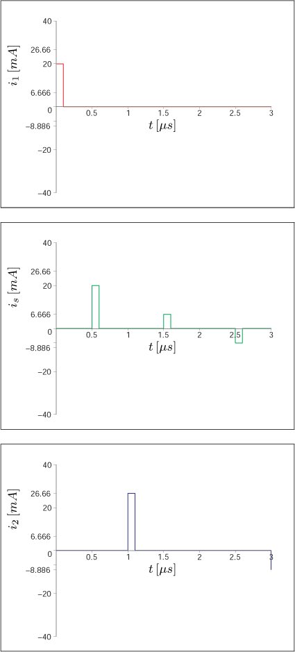
.The circuits contains ideal voltage controlled voltage source uv = K ur and they are in the steady state. Compute the output current waveform i 2(t) and its effective value I 2. Compute the active power, reactive power, apparent power and deformation power and the power factor of the output part of the circuit.
problem 1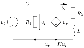  solution | problem 2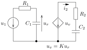 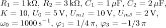 solution |
.The circuits contains ideal current controlled voltage source uv = R ir and they are in the steady state. Compute the output current waveform i2(t) and its effective value I2. Compute the active power, reactive power, apparent power and deformation power and the power factor of the output part of the circuit.
problem 1 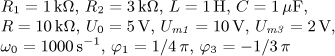 solution | problem 2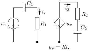 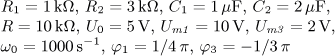 solution |
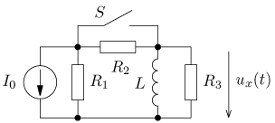
.The circuits contains ideal current controlled current source iv = H ir and they are in the steady state. Compute the output voltage waveform u 2(t) and its effective value U 2. Compute the active power, reactive power, apparent power and deformation power and the power factor of the output part of the circuit.
problem 1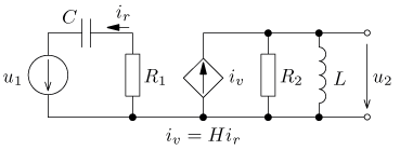 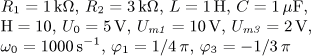 solution | problem 2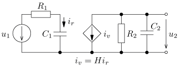 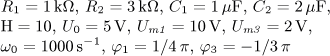 solution |
and they are in the steady state. Compute waveform of the output voltage u 2(t) and its effective value U 2. Compute the active power, reactive power, apparent power and deformation power and the power factor of the voltage source.
problem 1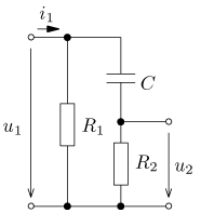 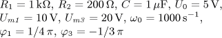 solution | problem 2  solution |
problem 3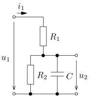  solution | problem 4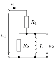  solution |
and they are in the steady state. Compute waveform of the output voltage u2(t) and its effective value U2. Compute the active power, reactive power, apparent power and deformation power and the power factor of the current source.
problem 1 solution | problem 2 solution |
problem 3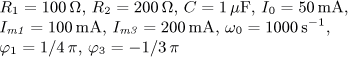 solution | problem 4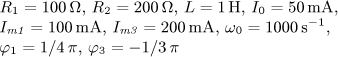 solution |
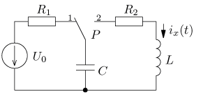
to obtain the
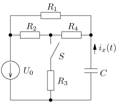
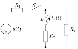
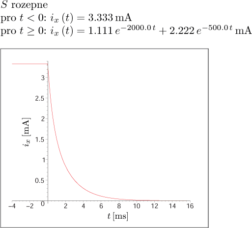
- current i(t ),
- voltage uc(t)
Fig. 1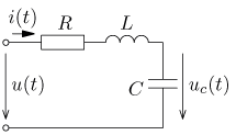  solution | Fig. 2 |
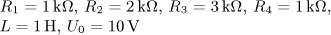
to obtain the
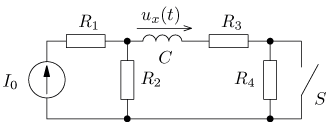
- voltage u(t),
- current ic(t)
Fig. 1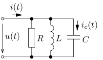  solution | Fig. 2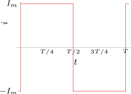 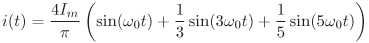 |
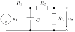
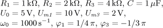
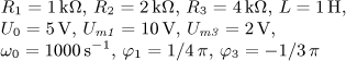
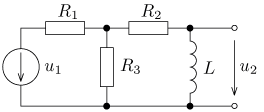
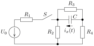
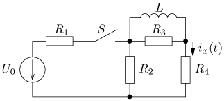
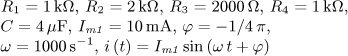
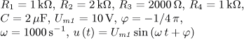
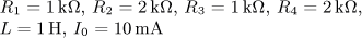
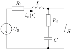
u(t) = U0 + Um1 sin( ω0t) + Um2 sin(2 ω0t) + Um3 sin(3 ω0t) [V].
Evaluate the waveform of the current i(t ) in the steady state and the active power of the source.
Fig. 1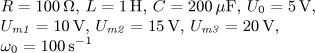 solution |
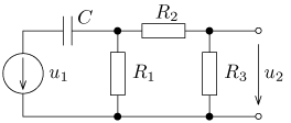
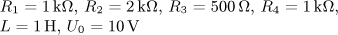
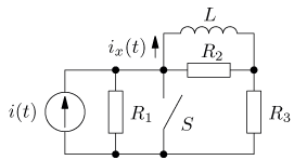
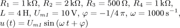
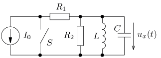
i(t) = I0 + Im1 sin( ω0t) + Im2 sin(2 ω0t) + Im3 sin(3 ω0t) [A].
Evaluate the waveform of the voltage u(t ) in the steady state and active power of the source.
Fig. 1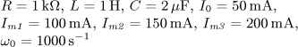 solution |


