Overview of questions:
- Specify all forms of Fourier series, which you know
- Specify equations for calculation of coefficients of sine-cosine and
rectangular form Fourier series
- Specify equations for calculation of coefficients of complex exponential
form Fourier series
- Define effective value of a periodic current (voltage) (root mean square
value)
- State effective value of a periodic current (voltage) that is represented
by a Fourier series
- Define active power of periodic non-sinusoidal voltage and current for
general two-port
- State formula for calculation of the active power of periodic
non-sinusoidal voltage and current of two-port, if voltage and current are
expressed by means of Fourier series coefficients
- State formula for calculation of the reactive power of periodic
non-sinusoidal voltage and current of two-port, if voltage and current are
expressed by means of Fourier series coefficients
- State formula for calculation of the apparent power of periodic
non-sinusoidal voltage and current of two-port, if voltage and current are
expressed by means of Fourier series coefficients
- State formula for calculation of the deformation power of periodic
non-sinusoidal voltage and current of two-port
- Describe how to derive Fourier transform of non-periodic variable by means
of generalization of formula for calculation of coefficients of the complex
exponential form of the Fourier series of periodic variable
- State for which classes of non-periodic signals their Fourier transform
exist
- Describe how is possible to extend class of functions, transformable by
Fourier transform using Laplace transform
- Write an Laplace transform of a function derivative
- Write an Laplace transform of a function integral
- Evaluate impedance of linear passive two-port passing through by
sinusoidal current
 with voltage across it in sinusoidal steady state
- Evaluate impedance of general linear passive two-port passing through by
general time function current i(t) and with general time function voltage u(t)
across it, if i(t) = 0 for
 and u(t) = 0 for
- Evaluate admittance of linear passive two-port passing through by
sinusoidal current it.gif with voltage across it in sinusoidal steady state
- Evaluate admittance of general linear passive two-port passing through by
general time function current i(t) and with general time function voltage u(t)
across it, if i(t) = 0 for and u(t) = 0 for
- Evaluate voltage transfer function of linear passive circuit supplied by
voltage source u1h.gif, if its sinusoidal steady state output voltage
- Evaluate voltage transfer function of general linear passive circuit
supplied by general time function voltage source u1(t) if its
output voltage is u2(t). Assume, that u1(t) = 0 for and
u2(t) = 0 for
- Draw the series equivalent circuit diagram of a charged capacitor, which
contains operational impedance and equivalent source of initial condition.
- Draw the parallel equivalent circuit diagram of a charged capacitor, which
contains operational admittance and equivalent source of initial condition.
- Draw the series equivalent circuit diagram of an inductor passing by
initial current iL(0+), which contains operational
impedance and equivalent source of initial condition.
- Draw the parallel equivalent circuit diagram of an inductor passing by
initial current iL(0+), which contains operational
admittance and equivalent source of initial condition.
- Write relations between Laplace transforms of current and voltage for a
linear resistor.
- Write relations between Laplace transforms of current and voltage for a
charged capacitor.
- Write relations between Laplace transforms of current and voltage for an
inductor passing by initial current iL(0+).
- Linear circuit is described by a diferential equation of the form
 Write the general
solution of this equation and its modification for excitation by constant (DC
sources) or by sinusoidal function.
Write the general
solution of this equation and its modification for excitation by constant (DC
sources) or by sinusoidal function.
- Linear circuit is described by a diferential equation of the form
Write the general
solution of this equation and its modification for excitation by sinusoidal
function.
- Linear circuit is described by a diferential equation
 Find its solution
for general initial condition ux(0+).
Find its solution
for general initial condition ux(0+).
- Linear circuit is described by a diferential equation
 Find its
solution if ix(0) = 0.
Find its
solution if ix(0) = 0.
- Linear circuit is described by a diferential equation
 Find its
solution if a characteristic equation has two different real roots l1, 2 , X0 = const.
Find its
solution if a characteristic equation has two different real roots l1, 2 , X0 = const.
- Linear circuit is described by a diferential equation
 Find its
solution if a characteristic equation has a repeated root l.
Find its
solution if a characteristic equation has a repeated root l.
- Linear circuit is described by a diferential equation Find its
solution if a characteristic equation has a complex conjugated roots
l1 = -a +
j w, l2
= -a + j w.
- Linear circuit contains m capacitors, which can't be grouped together, and
n inductors, which can't be grouped together. For this circuit describe
difference between energetic initial conditions and mathematical initial
conditions.
- Write the physical meaning of unit step response of a linear circuit.
- Evaluate generally unit step response of a linear circuit with input
variable x1(t) and output variable
x2(t).
- Evaluate unit step response of a linear circuit with input variable
x1(t) and output variable
x2(t) and write, how is possible to measure it.
- Evaluate generally unit impulse response of a linear circuit with input
variable x1(t) and output variable
x2(t).
- Evaluate unit impulse response of a linear circuit with input variable
x1(t) and output variable
x2(t) and write, how is possible to measure it.
- Which condition must met poles of a transfer function, if a unit impulse
response should be finite function (stable circuit, poles are only on the
left-hand side of the complex plane).
- Write, which parts (function types) can contain unit impulse
characteristic of a stable lumped circuit.
- Write the relation between unit step characteristic and unit impulse
characteristic of the same circuit.
- For circuit with transfer function P(p) =
U2(p)/U1(p) write general formulas for calculation of
the modulus and phase response (evaluation of a variables on vertical axeses
of that characteristics).
- Given the circuit with the transfer function
 . Draw the
asymptotic magnitude and phase frequency response in logarithmic coordinates.
. Draw the
asymptotic magnitude and phase frequency response in logarithmic coordinates.
- Given the circuit with the transfer function
 . Draw
the asymptotic magnitude and phase frequency response in logarithmic
coordinates.
. Draw
the asymptotic magnitude and phase frequency response in logarithmic
coordinates.
- Given the circuit with the transfer function
 . Draw the asymptotic
magnitude and phase frequency response in logarithmic coordinates.
. Draw the asymptotic
magnitude and phase frequency response in logarithmic coordinates.
- Given the circuit with the transfer function
 . Draw the asymptotic
magnitude and phase frequency response in logarithmic coordinates, if the
transfer function has 2 real negative poles p1, p2.
. Draw the asymptotic
magnitude and phase frequency response in logarithmic coordinates, if the
transfer function has 2 real negative poles p1, p2.
- Given the circuit with the unit step response
 . Draw the asymptotic
magnitude and phase frequency response in logarithmic coordinates.
. Draw the asymptotic
magnitude and phase frequency response in logarithmic coordinates.
- Given the circuit with the unit impulse response
 . Draw the asymptotic
magnitude and phase frequency response in logarithmic coordinates.
. Draw the asymptotic
magnitude and phase frequency response in logarithmic coordinates.
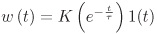
- Given the circuit whose unit impulse response is w(t).
Find in general its response u2(t) to the input
voltage u1(t).
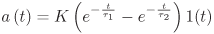
- Given the circuit whose unit step response of its voltage transfer
function is a(t). Find in general its response
u2(t) to the input voltage
u1(t) = Um 1(t) -
Um 1(t-t0) (rectangular
pulses of the width t0).
- Draw the elementary section of a homogeneous transmission line and deduce
its basic line equations.
- Write the wave equation of a homogeneous transmission line and its
solution.
- Prove, that wave equations are satisfied by the arbitrary function
u(x,t) =
f1(x-vt) +
f2(x+vt) for lossless transmission line.
- Write the equations for caltulation of the wave resistance and the
wave propagation speed along the line (wave velocity) of the homogeneous
lossless transmission line if you know primary parameters per unit length (L
and C).
- Define the reflection coefficient at the point of connection of two
transmission lines which have different wave resistances and write equation
for its calculation.
- Define the transmission coefficient at the point of connection of two
transmission lines which have different wave resistances and write equation
for its calculation.
- Find the reflection coefficient at the end of the open-circuited and
short-circuited transmission line.
- Find the reflection coefficient at the end of the transmission line loaded
by the resistor Rs with resistivity equal to the line's wave
resistivity R0.